Infrared Testing
Contact Our Certified Thermographers
Infrared Testing Services for Commercial Buildings In NYC and NJ
East Coast Industries, Inc. specializes in infrared testing a powerful tool allowing us to identify concealed issues the unaided eye could miss. Our advanced IR thermal-imaging technology helps us to identify heat anomalies and energy loss, serving commercial establishments in New York City, New Jersey, and the surrounding Tri-State Area, preventing costly repairs and system failures before they start.
Common Problems Infrared inspections Help Us Detect
- Overloaded components
- Imbalanced loads
- Loose connections
- Mechanical deficiencies.
This approach prevents equipment failures and electrical fires. Our infrared inspections could also identify roofing problems, moisture incursion behind walls, and insulation shortfalls causing energy loss and higher electrical costs. We give exact data free of invasive techniques or downtime by tracking temperature changes across electrical systems and building components.
Our knowledge is particularly beneficial in industrial buildings and NYC high-rises where sophisticated systems and large electrical loads demand close monitoring. Early detection of hidden inefficiencies and possible issues helps site managers to uphold safety standards, lower energy use, and prolong the life of vital equipment.
Count on East Coast Industries, Inc. to offer premium infrared testing services that maintain the safe and effective operation of your systems.
Get in touch
right now to arrange a visit and guard your business.
Professional Thermal Imaging Services For Accurate Diagnostics You Can Depend On
At East Coast Industries, Inc., we use thermal imaging electrical services to assist business properties in finding hidden problems that conventional inspections sometimes overlook. With high-resolution infrared cameras, specifically the Flir T420, known for its precision and reliability, while analyzing the data using state-of-the-art algorithms. This proactive approach improves the effective running of your systems and helps avoid expensive failures.
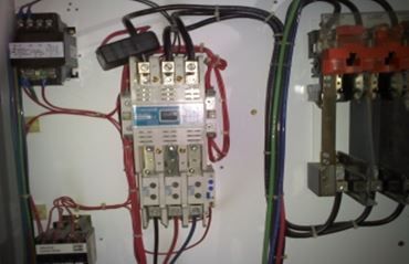
Infrared Electrical Inspections Commonly Monitor:
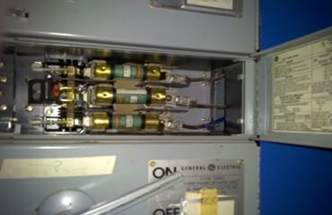
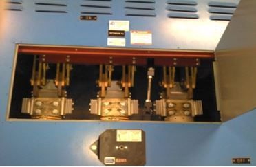
- Main Service Switchgear
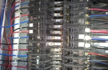
- Electrical panels
- PDU’s (Power Distribution Unit)
- Bus Duct Risers
- Bus Duct Disconnects
- Emergency Switchgear
- ATS’s (Automatic Transfer Switch)
- Generator Power, UPS’s (Uninterruptable Power System)
- HVAC systems
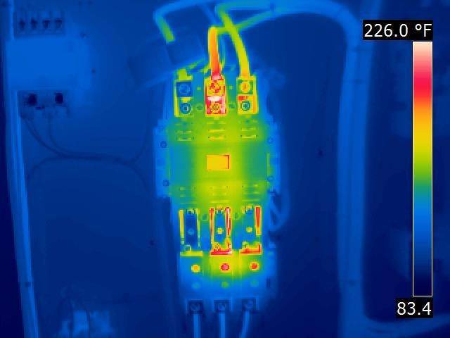
Finding overheated components using our thermal imaging technology enables facility managers to intervene before little problems cause big breakdowns. This lowers downtime and increases the lifetime of important equipment in addition to lowering the possibility of catastrophic breakdowns. Our reliable, real-time data from thermal imaging inspection enables smart maintenance plans and informed decision-making.
With respect to commercial properties, this approach is critically important. Whether managing a data center, manufacturing plant, high-rise office building, or other commercial property, thermal imaging ensures compliance with safety regulations and helps to optimize energy efficiency. This affordable choice increases system performance and reduces running costs.
Our goal at East Coast Industries, Inc. is to provide premium thermal imaging inspection services that safeguard your infrastructure and increase productivity. Contact us today to arrange an inspection and discover the value of sophisticated diagnostics.
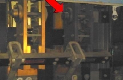
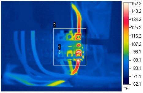
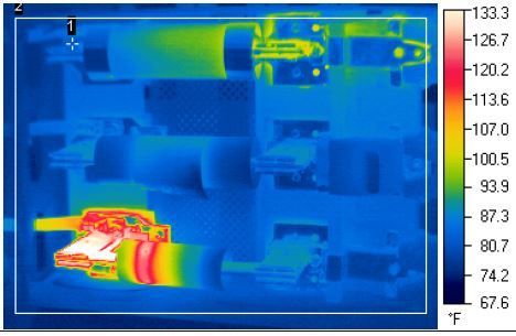
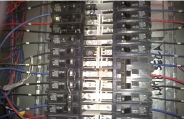
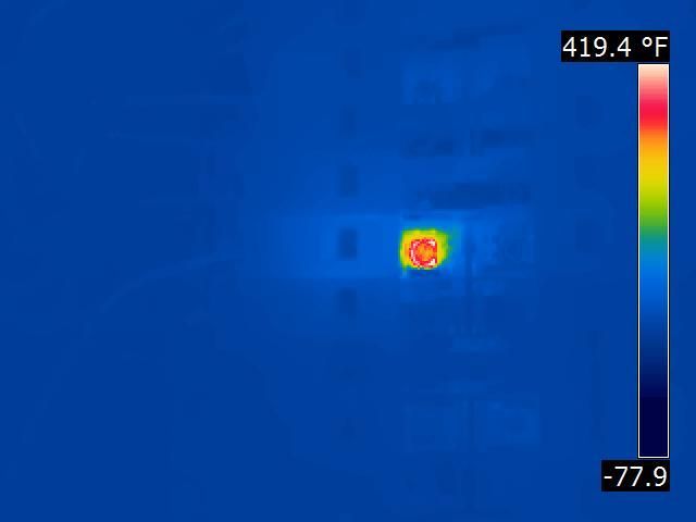
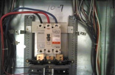
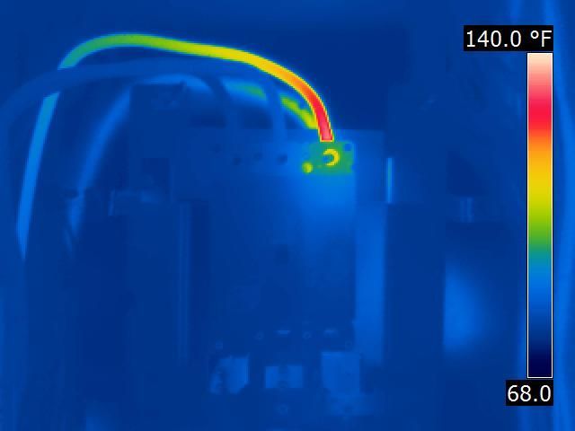
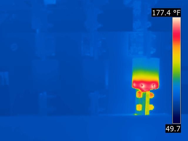
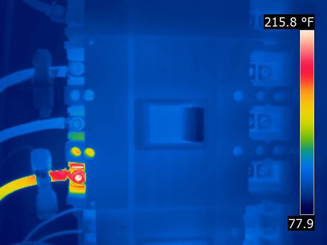
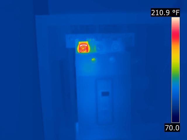
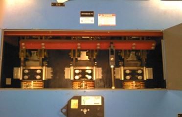
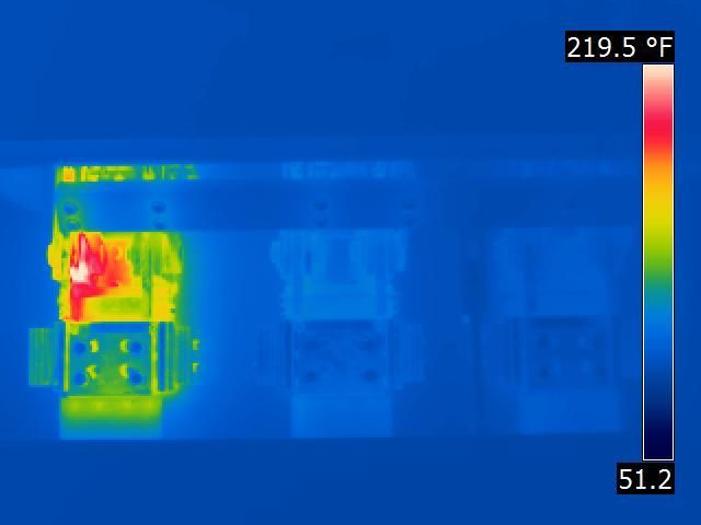
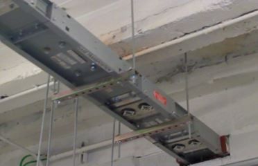
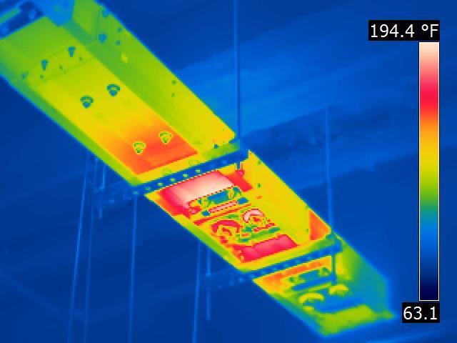
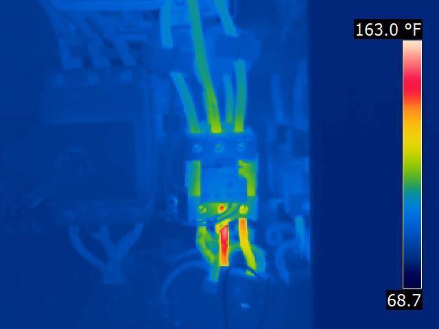
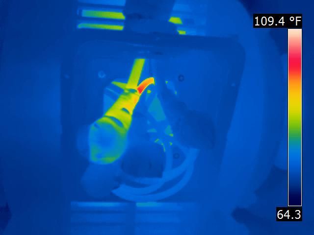
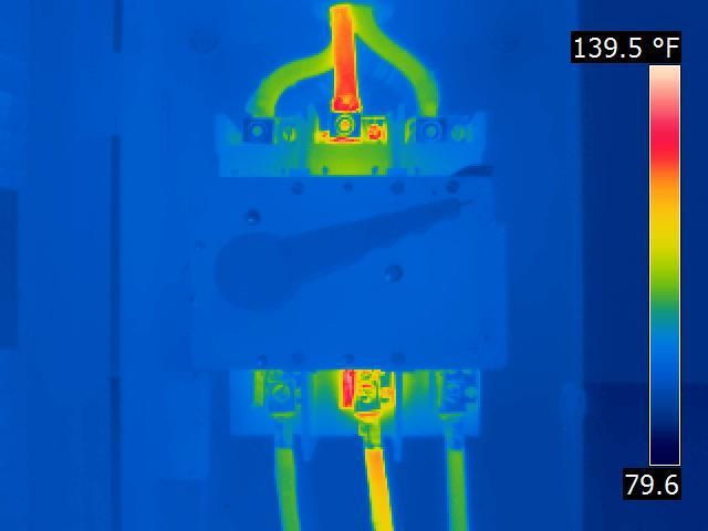
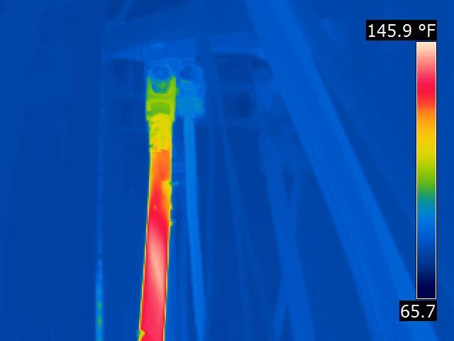
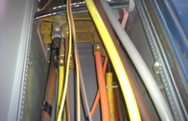
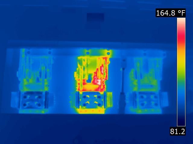
Case Study: Infrared Inspection in Action
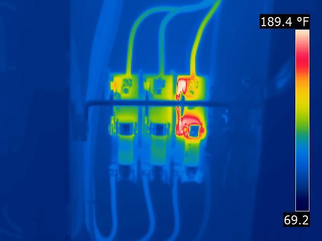
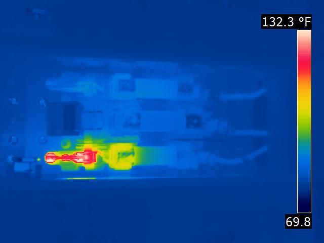
During an annual infrared inspection, ECI discovered a warm spot on a bus duct riser where a bus duct disconnect attaches. Because of this early detection, a proper shutdown and repair were performed, preventing possible unexpected downtime and added emergency repair costs.
Check out our other pages to learn more about services like
steam trap testing, vibration analysis,
power monitoring, and ultrasonic pipe testing
Ensure Safety with Precision Testing
Our precise, non-intrusive inspections help you detect issues early, ensuring safety, compliance, and long-term durability. Schedule your assessment today!
Thermal Infrared Testing Property Owners Count On To Prevent Costly Failures
In the hectic field of commercial infrastructure, spotting concealed problems before they become more serious is vital. Using infrared technology, East Coast Industries, Inc. helps business owners find structural flaws, energy inefficiencies, and electrical issues that would otherwise go undetected. Using infrared thermography gives reliable, real-time information that allows our customers make proactive decisions and lower the possibility of expensive mistakes.
What sets infrared technology apart is its adaptability to seamlessly fit into predictive maintenance schedules. Our high-resolution infrared cameras identify heat signatures and temperature variations in electrical panels, insulation, and mechanical systems.
With this information, we can pinpoint areas of energy loss, poor connections, and hotspots, which allows site managers to develop customized maintenance plans that prevent equipment failure and extend the life of critical systems. Additionally, our infrared thermography inspection services improve energy efficiency and safety compliance.
Our national scope and local knowledge have helped us to become the reliable choice for infrared technology solutions in the commercial sectors of NYC and NJ. From high-rise office buildings and industrial facilities to data centers and commercial complexes, we provide accurate and complete inspections that reduce downtime and safeguard your investment. Our staff is dedicated to delivering excellent service supported by years of industry expertise.
Do not wait until a small problem causes a significant disturbance. Count on East Coast Industries, Inc. for professional infrared thermography inspections to maintain the effective operation of your systems. Reach out to us today to arrange your inspection.
To know more about our services and how we can help you achieve running a business without interruption, choose us as your trusted partner in providing non destructive testing.
Benefits Of Infrared Testing
- Early Problem Detection: thermal imaging testing can identify problems that are not readily apparent to the human eye, such as loose connections, overheated parts, insulation gaps, and moisture incursion.
- Reduced Downtime: early detection helps avoid unplanned equipment failures and system shutdowns by detecting issues early, reducing expensive downtime.
- Significant Cost Savings: Preventative diagnostics dramatically reduce repair costs and energy usage by enabling early diagnosis and practive maintenance.
- Increased Safety: By detecting possible risks like electrical malfunctions and overheating parts, infrared inspections assist in creating a safer working environment.
- Increased Energy Efficiency: By identifying heat loss points in buildings, infrared thermography can help determine where energy is being wasted or where insulation is required.
- Longer Equipment Lifespan: infrared and thermal testing can help prolong the life of machinery and equipment by spotting possible problems early and taking appropriate action.
- Improved Maintenance Scheduling: infrared scan inspections yield useful information for enhancing maintenance plans and improving the economical and efficient use of resources.
- Increased Reliability: An Infrared electrical inspection lowers the chance of outages and disruptions in electrical systems by ensuring the dependability of power delivery.
- Improved Building Performance: Thermal inspection NDT can identify insulation problems, air leaks, and moisture intrusion during building inspections, improving comfort and energy efficiency.
- Non-Destructive (NDT) Testing: Since infrared NDT is non-destructive, it may be carried out without interfering with regular business activities or causing equipment damage.
- Objective Quality Assurance: To confirm the caliber of work and verify that repairs are completed accurately, infrared inspections can be utilized.
- Better Insurability: By lowering the chance of mishaps and equipment malfunctions, an IR electrical inspection can result in cheaper insurance rates.
- Informed Decision Making: The detailed reports generated by ECI's infrared scanning services give property owners valuable information for making informed decisions about maintenance and repairs.
Infrared Testing With Certified Thermographers - Levels I - II & III
Among leading NDT companies, we stand out for our use of high-resolution thermal cameras to detect critical system faults.